How to Apply GD&T Position Tolerance to a Hole
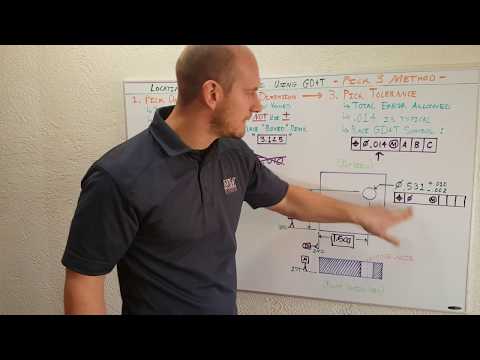
3-Second Blueprint (English)
- Establish primary, secondary, and tertiary datums (A, B, C) to constrain hole perpendicularity first and planar edge offsets next.
- Replace conventional plus/minus linear dimensions with boxed basic dimensions specifying exact theoretical distances from datums B and C.
- Place the positional tolerance zone and ordered datum references A-B-C in a GD&T feature control frame beneath the hole size callout.
GD&T Position ToleranceDatum Reference FrameBasic DimensionsFeature Control Frame
3-Sekunden-Fazit (Deutsch)
- Primäre, sekundäre und tertiäre Bezüge (A, B, C) festlegen, um zuerst die Rechtwinkligkeit der Bohrungsachse und dann Kantenmaße zu binden.
- Klassische Plus-Minus-Maße durch eingerahmte theoretisch genaue Maße ersetzen, die den exakten Sollabstand zu den Bezügen B und C angeben.
- Positionstoleranzzone und Bezugsreihenfolge A-B-C im Form- und Lagetoleranzrahmen direkt unter der Größenbemaßung der Bohrung eintragen.
GD&T PositionstoleranzBezugssystem (A-B-C)Theoretisch genaue MaßeToleranzrahmen
Note / Hinweis: Blueprints are AI-generated educational summaries (0% Politics · 0% Religion · 0% Brainrot) and do not constitute medical, legal, or financial advice. / KI-generierte Zusammenfassung zu Bildungszwecken – ersetzt keine medizinische, rechtliche oder finanzielle Fachberatung.