Astable 555 timer - 8-bit computer clock - part 1
3-Second Blueprint (English)
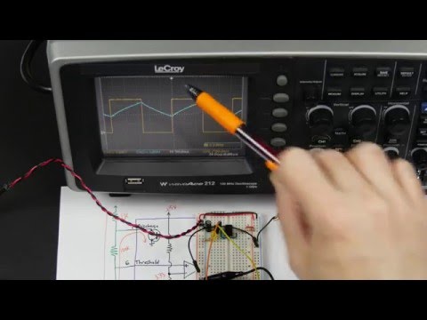
- Wires an astable 555 clock on a 5V breadboard using 1 kΩ and 100 kΩ resistors with a 1 µF timing capacitor.
- Three internal 5 kΩ resistors form a voltage divider setting comparator thresholds at 1.67 V and 3.33 V.
- Dual comparators toggle an internal SR latch as the capacitor charges and discharges to output steady clock pulses.
NE555 timer ICVoltage dividerVoltage comparatorSR latchRC timing circuit
3-Sekunden-Fazit (Deutsch)
- Baut einen astabilen 555-Taktgeber auf einem 5V-Steckbrett mit 1-kΩ- und 100-kΩ-Widerständen sowie 1-µF-Kondensator.
- Drei interne 5-kΩ-Widerstände bilden einen Spannungsteiler mit Komparatorschwellen bei 1,67 V und 3,33 V.
- Zwei Komparatoren schalten ein internes SR-Latch beim Laden und Entladen des Kondensators für stabile Taktimpulse.
NE555-Timer-ICSpannungsteilerKomparatorSR-LatchRC-Zeitglied
Note / Hinweis: Blueprints are AI-generated educational summaries (0% Politics · 0% Religion · 0% Brainrot) and do not constitute medical, legal, or financial advice. / KI-generierte Zusammenfassung zu Bildungszwecken – ersetzt keine medizinische, rechtliche oder finanzielle Fachberatung.